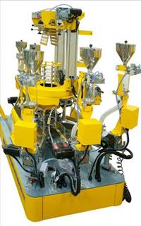
NEW
Scientific
Mini
3
and 5 layers
Co-Extrusion
Film Blowing Line Type LMF-200
CO-EX
with 3 and 5 Extruders respectively
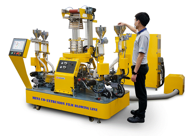


WITH 16 MM, 30 L/D EXTRUDERS FOR PROCESSING MANY RESIN TYPES AND
ALLOWING OPTIMUM DISPERSION OF ADDITIVE MASTERBATCHEES
 Our
new
Mini
LMF-200
CO-EX
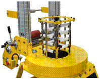
film blowing line
is a viable low-cost alternative to our regular co-ex
film blowing lines.
The line has either 3 or 5 extruders of lowboy-type connected to their
respective 3 and 5 layer pancake-type film blowing dies.
The line is also equipped with an oscillating nip-roll as the the
standard haul-off system where the entire film tower including the
wind-up section oscillates
360° back and forth over the die assembly.
Our
new
Mini
LMF-200
CO-EX
film blowing line
is a viable low-cost alternative to our regular co-ex
film blowing lines.
The line has either 3 or 5 extruders of lowboy-type connected to their
respective 3 and 5 layer pancake-type film blowing dies.
The line is also equipped with an oscillating nip-roll as the the
standard haul-off system where the entire film tower including the
wind-up section oscillates
360° back and forth over the die assembly.
THE LINE FEATURES:
¨
Compact design taking up a minimum of floor space of only 1.9 x 1 m.
(6.2 x 3.3 ft) plus electric cabinet of 1.1 x 0.4 m ( 3.6x1.3 ft )
¨
The entire line is mounted on a sturdy steel podium eliminating the need
to secure the extruders and tower to the floor. The steel platform
containing all major supply cables, hoses, and air ducts gives a very
clean appearance with very few visible connections to the extruders and
the tower.
¨
Tower assembly is mounted on
bearing rails, enabling easy access to the die and air ring.
¨
Lowboy
type extruders are aligned to the low height of the die for convenient
assembly and operation.
¨
Modular pancake die assembly of custom design in consultation with our
Canadian expert designer for optimum co-ex
film applications using your specific
types of polymer.
¨
Air ring for
optimum cooling efficiency.
¨
Easily adjustable stabilizing cage with Teflon rollers for various film
bubble diameters.
¨
Compact oscillating film tower which greatly minimizes
the effects of film gauge variations
for quality film rolls.
¨
Surface wind-up station with air shafts for easy changeover of rolls.
¨
The machines are designed to occupy minimum space and to optimize the
workspace.
¨
Fully computerized
LMF-200
CO-EX
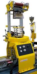
Compact Film Blowing Tower
Tower Structure
·
Assembled on a heavy-duty
steel support frame fixed on a steel base floor. The standard height
from floor to nip-rolls is only 1.9 meter (6.2 ft) making it very easy
for operator to thread the film
·
Height from die lip to Nip-Rolls 104 cm (3.4 ft)
·
The nip roll width is 200 mm with 180 mm maximum film lay-flat width.
·
Equipped with four guide rollers down stream to maintain suitable
tension before windup.
Air Ring and Blower
§
 High
efficiency cooling ring with optimum cooling efficiency and high
stability of the film bubble.
High
efficiency cooling ring with optimum cooling efficiency and high
stability of the film bubble.
§
Supplied with a streamlined air distribution manifold.
§
The cooling air is supplied from a variable speed 0.37
kW turbo blower. The RPM of the blower is
controlled with a turning knob on the tower’s control panel and is
regulated by an AC frequency inverter.
§
The fan speed regulation optimizes the cooling of the film.
Streamlined air distribution nozzles ensure an even airflow all
around the cooling ring.
§
Equipped with analogue air pressure and air temperature meter
§
Four flexible hoses connected to the air ring from the distribution
manifold and blower.
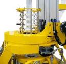
Bubble Stabilizing Cage
·
Four levels of cage arms covered with free-rotating Teflon rollers.
·
 Easily
adjustable cage size via a
knob for various film bubble diameters where all Teflon roller arms are
moved synchronously.
Easily
adjustable cage size via a
knob for various film bubble diameters where all Teflon roller arms are
moved synchronously.
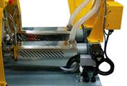
 Tower
with Collapsing Frame and Haul-off
Nip Rolls
Tower
with Collapsing Frame and Haul-off
Nip Rolls
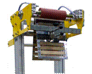
·
Collapsing frame
consists of polished teak wood slats for smooth guiding of delicate
films.
·
Pneumatically-operated
nip rolls
consisting of a wear-resistant
rubber idle lay-on
roll and a
hard-chromed
surface polished roll driven by a heavy-duty,
infinitely-variable-speed
servo motor drive and inverter.
Surface Winder
·
Standard surface wind-up
system
with rubber lay-on
roll and a polishing roll driven by an independent variable-speed
servo motor drive with constant torque for quality film roll winding.
·
Separate
3
inch
free-rolling,
windup air shaft
mounted on the windup rack for easier bobbin handling
(Customer
is provided with one unit.
Additional air shafts are available to order).
Equipped as standard with Compact 360° Oscillating Tower
for effective minimizing of film gauge variance
·
 The
newly introduced
oscillating tower frame
has a rotary base mounted on a gear assembly driven by a servo drive
motor for a full 360° oscillation of
the stabilizing cage, collapsing frame and the haul-off
nip-rolls to counteract
and effectively minimize film gauge variance occurring during the film
blowing. For high-quality film winding with a uniform film roll geometry.
The
newly introduced
oscillating tower frame
has a rotary base mounted on a gear assembly driven by a servo drive
motor for a full 360° oscillation of
the stabilizing cage, collapsing frame and the haul-off
nip-rolls to counteract
and effectively minimize film gauge variance occurring during the film
blowing. For high-quality film winding with a uniform film roll geometry.
·
Simple and smart design uses few moving parts, allowing for easier
handling and maintenance.
Multilayer Film Blowing Pancake Die Assembly for CO-EX
Lines
LPD20-40
Die Design
¨
Modular die assembly with 5 pancake die layers, each made of high grade
tool steel and with low-friction
nickel coating and mirror polished channels and mandrels for optimum
melt flow performance.
Features annular die lip diameter sizes ranging from 20 to 40 mm with
easily changeable mandrels suitable for use with
Labtech’s
16 mm single screw extruders.
(Different
die lip rings and mandrels sizes supplied according to customer’s
specific resin types and layer configuration)
¨
We custom design our dies in full conformity to customers’ requirements
with consultation from Dr.
John Perdikoulias of Compuplas, Canada.
This ensures a die design with optimal rheological performance and
compatibility in accordance to all polymers specified by the customer.
The binary distribution and spiral flow channels leading to the mandrel
have been analyzed using the latest software analysis technology to
optimize the flow properties throughout the entire die and achieving a
very efficient, uniform distribution of the melt in each layer.
Optimized Melt Flow Channels
·
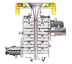 Melt
from the feed ports, coming from the extruders, flows into the outer
edge channel of the pancake die, which is then repeatedly divided into
binary flow distribution channels
(2,
4, 8 and so on)
ending with multiple channels running around the die for optimum
flow distribution.
As they flow near the centre, they enter a spiral flow pattern before
converging back together into a single annular area with uniform volume
and distribution around the die mandrel, which greatly improves the
uniformity and consistency of each layer thickness.
Melt
from the feed ports, coming from the extruders, flows into the outer
edge channel of the pancake die, which is then repeatedly divided into
binary flow distribution channels
(2,
4, 8 and so on)
ending with multiple channels running around the die for optimum
flow distribution.
As they flow near the centre, they enter a spiral flow pattern before
converging back together into a single annular area with uniform volume
and distribution around the die mandrel, which greatly improves the
uniformity and consistency of each layer thickness.
·
The melt then flows upwards combined with the other layers in a laminar
fashion along the mandrel towards the die exit where the film is
externally cooled and blown into a bubble with uniform wall thickness.
The die is also equipped with centering bolts for adjusting the die
centre position relative to the mandrel for fine tuning the bubble’s
thickness uniformity.
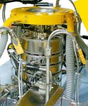 Co-Extrusion
Die Assembly
Co-Extrusion
Die Assembly
¨
The 3 or 5 die layers are supplied for the LMF-200
CO-EX
line.
Each layer has feed ports into which high-pressure,
heated adaptors are attached for connecting to designated extruders.
¨
The adaptors are equipped with heating bands and thermocouples
(fitted
in the mid-section)
for monitoring and regulating temperatures up to 300°C.
¨
Individual thermocouples and heater bands for each die layer (module)
allows for individual monitoring and temperature control up to 300°C.
Each layer is partially isolated from the next layer to minimize heat
transfer from one layer to another.
¨
All temperature-controlled
parts are monitored and set on the LCC computerized touch screen control
panel.
Thermocouples and heater band cables are organized and connected to a
separate signal control cabinet that comes with the assembly.
|
Price in US$ for die core mandrel |
|
|
Die type |
Die LPD20-40 |
|
Suitable for COEX Film Tower type : |
LMF-200 |
|
Converting form 3 layers to 1 layer |
690 |
|
Converting form 5 layers to 1 layer |
920 |
|
Converting form 5 layers to 3 layers |
860 |
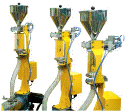
30 L/D
Mini
Single-Screw
Extruders
with 16 mm Diameter
Type LME16-30/C-HA
Mini
non-vented
extruders for processing all available types of film blowing resins
General Design
·
New
“Single
Pillar”
versions where the barrel and motor drive is mounted on a single heavy-duty
pillar support.
The lowboy cantilever barrel design conveniently fits into the lower
pancake layer (module) positions for more convenient assembly of the
heated pipes to the die.
·
Narrow and streamlined body
minimizes space consumption
for easy maintenance.
·
Heavy-duty,
compact base for securing the fixture to the base platform.
·
C-clamp
on the terminal flange allows for quick and secure connection to adaptor
pipes and die layers
·
Extruder can easily be swung to the side for removal of the screw. And
for purging
·
Internal and external steel parts coated with heavy duty epoxy paint.
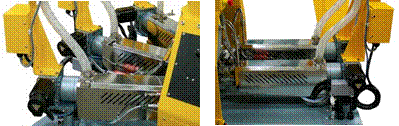 Barrel
and Screw
Barrel
and Screw
·
Barrel and screw
made of high-grade
quality steel with
nitride hardened surface
·
The 16 mm screws are with an L/D
of 30
·
Full stainless steel cover over the barrel with air venting grilles on
th
e sides.
Barrel Heating and Cooling System
·
2 thermo-regulated
barrel zones for the 16 mm diameter extruder.
·
Each zone with high wattage heaters and efficient cooling fan.
·
Standard maximum heating temperature of 300°C and an optional 400°C max
for high-heat version.
·
Water-cooled
feed section to prevent premature melting of resins
Infinitely Variable-Speed
Servo Motor Drives on all extruders
¨
High performance vector drive motor with high torque through the entire
speed range for precise feed-rate
of melt to the die layer resulting in a high layer thickness precision
and better tolerances even at low feed-rates.
The servo drive motor allows for infinitely variable speed adjustments
from 0 up to the 150 RPM max ensuring a very even resin flow at low RPM
which is particularly important to obtain very thin film layers.
¨
Screw shaft driven by a reducer gearbox mounted directly on a heavy-duty
thrust bearing housing
Touch Screen Control Interface
¨
The entire line with extruders and optional gravimetric feeders as well
as die layers and downstream equipment is fully computerized and
controlled on a large touch screen.
The touch screen is mounted on a free standing cabinet.
Hopper
¨
Polished stainless steel hopper with lid mounted on a slide valve plate.
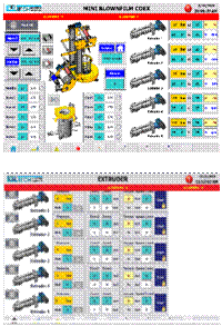
Technical Data for Mini
Single-Screw Extruders
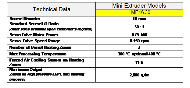
Maximum Output at 150 RPM with our 16 mm Single-Screw Extruder
LE 16-30 (kg/hr)
|
POLYMER TYPE
(Regular pellets) |
HDPE |
PET |
PMMA |
NYLON |
GPPS |
ABS |
PP |
EVOH |
LLDPE |
LDPE |
PLA |
PC |
|
Maximum Output
(kg/hr) |
1.7 |
2.7 |
2.7 |
2.1 |
2.4 |
2.6 |
1.8 |
2.7 |
1.9 |
2.0 |
2.5 |
2.7 |
|
% of Maximum Motor Power |
80 |
61 |
60 |
30 |
38 |
58 |
57 |
64 |
90 |
65 |
80 |
91 |
Computerized
Central Control Unit
·
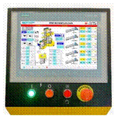 Features
a
12 inch
LCD touch screen control panel
mounted on a sturdy,
fixed control
stand with a sleek design and an angled display for comfortable viewing
of line parameters on
Labtech’s
fully computerized control interface for the
LMF-200
CO-EX
Features
a
12 inch
LCD touch screen control panel
mounted on a sturdy,
fixed control
stand with a sleek design and an angled display for comfortable viewing
of line parameters on
Labtech’s
fully computerized control interface for the
LMF-200
CO-EX
·
PLC with large processing capacity allows interface connection with
multiple extruders, blowers, and the die assembly.
Supplied complete and wired to all components of the film blowing line.
·
Temperature control and monitoring
of all thermoregulated zones in the line.
·
Speed controls
for the extruders, nip rolls (haul-off), and blower units.
¨
 Supports
various drive speed control modes for the extruders.
Supports
various drive speed control modes for the extruders.
¨
Sync Co-Ex:
Master-slave
extruder synchronized control.
¨
LIW
(loss-in-weight)
auto-override
of drive speed for constant feed rate
(only
applicable for extruders equipped with the optional gravimetric
hopper-feeder system).
¨
Sync LF:
auto-sync
tower haul-off
and pull rolls with extruder drive speeds.
·
Generation of real-time
graph trends
of processing temperatures and speeds for comprehensive parameter
monitoring and quality control.
-
Integrated alarm system and real-time
system diagnostics
with user notifications for easier troubleshooting of the line.
-
Save and load pre-set
parameters on internal and external memory with the
RECIPE feature.
-
Secure supervisory control with
Authorized User Control Protection
feature which restricts access to advanced settings of the line.
Gravimetric Hopper feeder controls are incorporated on same touch screen
as the central control unit
The weighing hoppers are controlled on the main LCD color touch screen
panel with easy to read and understand graphics.
All feeding parameters for the weighing
hopper units are easily keyed in on the panel where you also have
screens showing real time data, etc.
OPTION:
Weighing
Hopper Feeder with Computerized Control System
for precise control of individual layer thickness and distribution to
the die assembly
In order to achieve a precise control of the layer thickness in co-extrusion
lines, each layer needs to be fed with a precise amount of resin.
This can best be achieved by using our weighing hopper system.
Our very favourable priced and very accurate system features our
computerized
loss-in-weight
(LIW)
type weighing hopper
system, where each extruder hopper will deliver a user-set
amount of resin
(in
weight units per minute),
in which the feed rate is simply keyed into the touch screen central
control unit.
The central control unit has a setup screen, where you can set all the
required feed rates for each individual weighing hopper as well as the
layer ratio, thickness and even the total system output
(kg/hr).
Density values for the various resins can be inputted to enhance
automatic layer ratio control.
The control panel has a multitude of screens with various functions and
a graphic illustrations of the extrusion control trends.
The system is connected in a closed loop system with the extruder drive
speed control.
Thus, when keying in the exact feed rate on the central control panel
for a specific extruder, the weighing hopper on the extruder will sense
the amount being fed to it, and the controller automatically regulates
the screw RPM so that it feeds exactly the amount of weight units per
minute as previously set on the panel.
If the control system is linked with the LCC Central Control Unit as a
sub-system,
the
LIW
speed control mode
is integrated on the LCC control panel where it can be enabled and
disabled.
Weighing Hopper Features
·
The weighing hopper incorporates a precision load cell for accurate
sensing of the hopper weight.
·
Above the weighing hopper is a stainless-steel
refill hopper mounted on top with a pneumatic slide gate which will open
automatically to refill the feeder tank whenever the material level is
low.
·
The weighing hopper has a
volumetric capacity of 2.2 liters and a
material weight capacity of 1.5
kg of pellets.
·
The refill hopper has the same volume as our regular extruder hoppers
and is also equipped with a sight mirror for easy viewing of the resin
level.
·
The maximum feed rate of the weighing hopper is 1 kg/hr.